")

As already announced in part 1 of this article, we now illuminate the different bus types. As a reminder, it was the I2C Bus, the ISCANTM and the DiveCAN® installed in rebreathers.
The I2C bus are in Seabear products and AP Diving Rebreathers, i.e. the Inspiration XPD, the Inspiration EVP (formerly known as Evolution+) and the Inspiration EVO (also known as Evolution).
The rebreathers from Innerspace System Corp., the Megalodon CCR and the Pathfinder CCR use the ISCANTM
The DiveCAN® is installed in all rebreathers that use Shearwater electronics. These are for example the JJ-CCR, the rEvo, the Hollis Prism2, the SF2 and the O2ptima. The newest member in these family is the XCCR.
I2C Bus
Let’s consider first the I2C bus because this is the one that has been used longest in rebreathers. When pronounced, I2C means Inter-Integrated Circuit.
It was developed by Philips in the 80s to establish simple communication between electrical components. Each of you has come into contact with this bus several times without knowing it, and carry it with you every day in your wallet. The bank card chips use this bus. The I2C bus is also used in televisions and CD players. Since the introduction of Vision Electronics in 2005, this bus has been used by AP-Diving. It allows a transfer speed of 1 Mbps, as fast as DSL in the middle of the 2000s. Up to 1136 devices can be connected to this bus! The I2C bus requires a clock line (called Serial Clock, SCL) and a data line (Serial Data, SDA). The clock signal required by each bus is transmitted over the clock line. The I2C bus is a multi-master bus in that any device on the bus can be a master, but there can only be one master at a time. Bit by bit arbitration ensures only one master during each message. The master provides the clock and controls the sending and receiving of data to and from the slave(s). The actual data is transferred via the SDA, the data line. The I2C bus operates with positive logic. In this case, information is transmitted by means of voltage levels, for example a voltage of 5 V corresponds to a HIGH signal, i.e. a logical 1, no voltage (i.e. 0 V) corresponds to a low level and thus to a logical 0.
The following figure shows the example of an information packet in the I2C Bus.

I2C-bus, source: www.i2c-bus.org
We do not want to take the whole picture apart, however it is important to say that the beginning of a packet is always provided with a start signal and the end of a packet with a stop signal. How these signals look is defined in the Layer 2 (Data Link Layer) of the ISO / OSI model.
The start of data transfer, the start condition, by an I2C master looks as follows:
The master pulls the data line (SDA) down from HIGH to LOW while the clock line (SCL) remains HIGH. In between, the actual data are then transmitted. A data bit can, as is usual in digital technology, be in one of 2 states, 1 and 0 or simple voltage or no voltage. The data are valid when the clock line (SCL) is set to HIGH. A LOW level on the data line (SDA) means 0, a HIGH means 1, which is positive logic as previously described. The information packet is ended by the stop condition. The master pulls the data line (SDA) from LOW to HIGH, while the clock line (SCL) remains set to HIGH. The transfer is then complete. From the point of view of the I2C master, read and write sequences can be differentiated. In a read sequence, the I2C master reads data from the slave. In a write sequence, the I2C master sends data to the slave. This is important because in a rebreather, the data made available by a CO2 sensor for example, must be read and interpreted by the controller.
In the AP Diving Inspiration the I2C bus is implemented as in the following graphic.
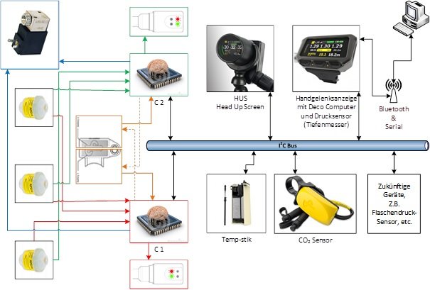
Controllers C1 and C2 (chips embedded in the head of the Inspiration) are the main control units in this environment. In this case, only one controller (usually C1) can be the master, the other controller (C2) remains the slave. Both controllers monitor each other. If the master controller fails, the slave controller automatically becomes the master. The unique AP hardware implementation provides bus isolation from any malfunctioning device so that the remaining devices can communicate fully without interference. Also the robust software filtering and protocols ensure only correct processing of data and commands
DiveCAN® + ISCAN TM
In this part I summarise the DiveCAN® and the ISCANTM since both are very similar and have the same origin, the CAN bus.
CAN stands for Controller Area Network and was developed for the vehicle industry. In part 1, I have already written about the requirements of the automotive industry, so I do not want to go into it any further. The CAN bus was developed in cooperation with Bosch and Intel. It is now widely used in other branches of industry. Fire extinguishing systems are implemented via FIRECAN. E-bikes use the EnergyBUS, jet fighters and civilian airplanes use the CANAEROSPACE, which are all based on the CAN bus.
The cable used in the CAN bus is a two core, twisted pair cable with a diameter of 0.35 mm2. The ends of the bus must be terminated with 120 Ohm terminating resistors
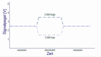 The signals are applied to both lines at the same time, but with an inverse power change. There are 2 signal levels CAN HIGH and CAN LOW. How these signals are displayed depends on whether it is a high speed CAN or low speed CAN. The DiveCAN® uses the high-speed CAN according to ISO 11898-2 so we will only shed some light on this one. There is a recessive signal and a dominant signal. In the recessive, the voltage on both lines is 2.5V. This corresponds to a logical 1.
CAN-bus levels, source: Lawrenz W., CAN Grundlagen und Praxis
For a dominant signal, the level on the CAN HIGH must be raised to 3.5 V and lowered to 1.5 V on the CAN LOW. This represents the logical 0. So if the voltage on both lines is equal, it is a 1. With a voltage difference of 2 V between CAN HIGH and CAN LOW, it is a 0. This is the exact opposite of the I2C bus and is called negative logic
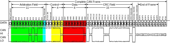
CAN-bus frame, source: www.wikipedia.de
The actual data transmission takes place in so-called frames (see picture above). These always have a start frame, which is always a logical 0. Then the data are transferred. Here too, there are further subdivisions within the frame, which I don’t want to discuss as it goes beyond the scope of what we want to do here. It is important to note that a frame end is always represented with a 7-bit recessive signal, that is, 7 consecutive 1s.
 Shearwater Research has only utilised this type of bus and developed the above-mentioned DiveCAN® on it, which has been specifically adapted to the needs of the closed circuit diving apparatus. It is also based, as already mentioned, on the ISO 11898-2 standard. It is however specifically adapted to the manufacturer (proprietary). Shearwater use for example a 560 Ohm terminating resistors that allows only 9 devices to connect. Furthermore, a DiveCAN® controller of an rEvo would not work with a JJ-CCR, although they both use the DiveCAN®. The reason for this is quite simple, every rebreather expects certain devices connected to its bus.
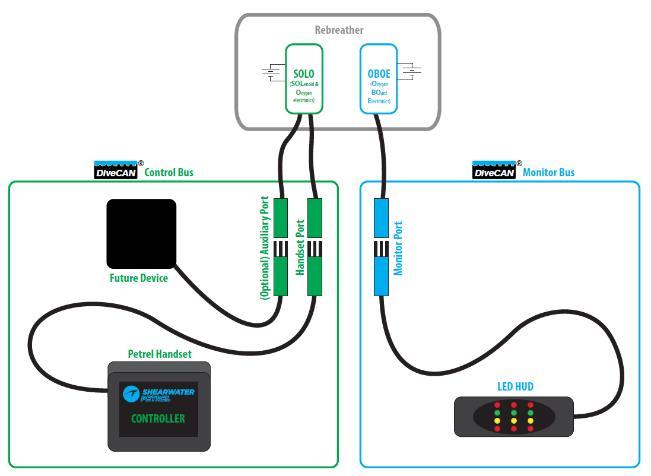
Schema DiveCAN bus, source: www.shearwater.com
The DiveCAN can prioritise the data packets and is able to transfer the data in real time. A warning message in the DiveCAN® has the messageID "0x02", whereas the pO2 has the message ID "0x04". The ambient pressure / depth has the message ID "0x08". The lower the message ID, the more important is the message. In this case, the warning message would always be transmitted and displayed by the bus before the pO2. Only after this 2 information would the current depth be transferred and displayed.
But how is a DiveCAN® system built up?
The minimum configuration would be only one bus, namely the Control Bus. However, since most Rebreathers attach importance to redundant systems, a second independent bus is installed, the monitoring bus. Both are located in the same housing, but they are separate and completely independent of each other.
The DiveCAN® Control Bus
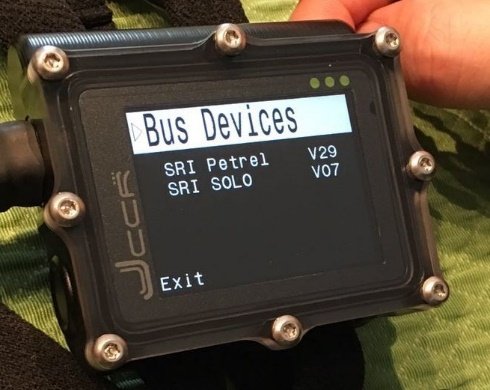
The control bus consists of the SOLO board (Solenoid & Oxygen) and the controller. The SOLO board has connections to the oxygen sensors and to the solenoid. The bus can be extended via an optional port, the Auxiliary Port. Additional devices may be connected to it as well, e.g. a scrubber monitor. If the devices connected to the bus are shown on the Shearwater Petrel, the following output is displayed.
The DiveCAN® Monitoring Bus
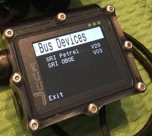
The monitoring bus is a stand-alone bus that has no connection to the control bus. It is connected to the OBOE (Οxygen Board Electronic). This board only has access to oxygen sensors, and has no access to the solenoid. As the name suggests, it has a purely monitoring function. If you connect a controller or a NERD to this bus, you can also see which devices are connected and you get this display.
Both buses are high-speed buses and can thus achieve a transmission rate of up to 3 Mbit. Therefore all system critical functions have redundancy. For example, the SOLO board can control the solenoid in the event the connected controller has failed. Signals sent on the bus are either received correctly or discarded immediately. Thus, processing of erroneous values is ruled out.
In the eCC rebreathers this technology is indispensable. In my opinion, it is a huge step forward in safety. It simply minimises error sources and dramatically reduces the task load of the diver in stressful situations. This technology also opens the way for the future in order to connect and easily integrate new devices and extensions. For example, cylinder pressure sensors, temperature sensors or near-field communication could all be connected to the bus systems.
Despite all the great techniques described here, the rebreather diver still has to know and understand the functioning of his rebreather! Training the emergency skills must continue and a diver should always put on his/her thinking cap before diving! Despite all their high-tech value, bus systems will not be able to replace the need for clear thinking and knowledge from a diver.